|

MCPCB
Introduction 
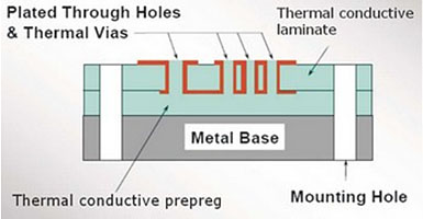
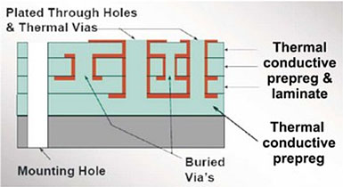
As Metal Core PCB means the base material for PCB is metal, but not normal FR4/CEM1-3, etc, and currently what the metal used are Aluminum, Copper alloy. MCPCBs are used instead of traditional FR4 or CEM3 PCBs because of the ability to efficiently dissipate heat away from the components. This is achieved by using a Thermally Conductive Dielectric Layer. The main difference between a FR4 board and MCPCB is the thermally conductive dielectric material in the MCPCB.
Main Application 
Power Supply、ABS、Engine Control Module、Lighting Fixture、Back light Module
Specification 
| ITEM |
UNIT |
STANDARD |
SPECIAL |
| Layer Count |
Layers |
1-2 |
Max. 4 |
| Total Thickness (Min/Max) |
W/m.L |
2.5 |
4 |
Thickness
(Min/Max)
|
Cu Foil |
oz |
1-2 |
0.5/6 |
| Insulation |
mm |
100 |
80/150 |
| Base Metal |
mm |
1.0-2.0 |
0.6/3.0 |
| Panel size |
mm |
510*610 |
Max.~740 |
| Surface Treatment |
|
OSP/ENIG/TIN |
|
Layer Structure 
• Single Layer MCPCB

• Double Layers MCPCB

• Double Sided MCPCB

• Multi Layers MCPCB
 |

